Actuated Gate Valves Explained: Direct Answer First
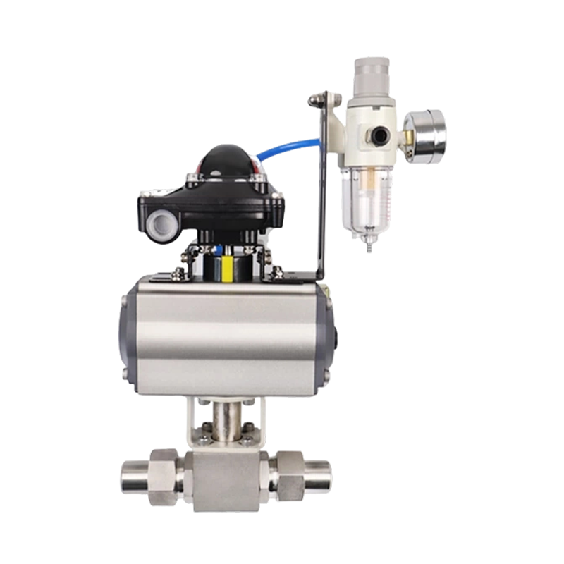
An actuated gate valve is a standard gate valve fitted with an electric, pneumatic, or hydraulic actuator that opens and closes the gate automatically instead of relying on a handwheel. The actuator replaces manual torque with motor-driven, air-driven, or fluid-driven force, which lets the valve respond to a control signal from a PLC, DCS, or local control panel. Because a gate valve is a linear, multi-turn device, the actuator must be matched to the stem travel and torque profile of that specific valve, not just bolted on as a generic accessory.
The short answer to why facilities choose actuation is consistency. A gate valve operated by hand can be left half-open by accident, closed with inconsistent torque, or simply forgotten during a shift change. An actuated gate valve closes to the same position every time, reports its status back to a control room, and can be interlocked with safety systems so it shuts automatically if a sensor trips. This combination of repeatable positioning and remote feedback is the main reason actuated gate valves dominate isolation duty in pipelines, water treatment plants, and process industries.
There is also a labor and access argument that gets less attention than the safety argument but matters just as much in practice. Many gate valves sit in locations that are inconvenient or hazardous to reach by hand: buried vaults, elevated pipe racks, rooftop mechanical rooms, or confined spaces inside a treatment basin. Sending a technician to manually operate a valve in one of these locations costs time and introduces fall, confined-space, or lockout risk every single time the valve needs to move. Actuation removes that recurring exposure entirely once the initial installation is complete, which is part of why retrofit demand for actuators on existing manual gate valves has stayed strong even in facilities that are not adding new piping.
The rest of this article works through actuator types, sizing logic, materials, applications, control architecture, failure modes, troubleshooting, cost considerations, and maintenance intervals, with data points framed against manufacturer engineering guides and field studies so each claim has a traceable basis rather than a generic summary. Readers looking for a quick installation reference can jump to the selection checklist near the end, while readers troubleshooting an existing valve may want to go directly to the failure modes and troubleshooting sections.
Actuator Types Used on Gate Valves
Three actuator families cover almost all actuated gate valve installations: electric, pneumatic, and hydraulic. Each one converts a different energy source into the rotary or linear motion a gate valve stem needs, and the choice between them is rarely about preference alone.
Electric Actuators
Electric actuators use a motor, gearbox, and limit switch assembly to turn the valve stem through its full travel. They are the most common choice for gate valves in water distribution, HVAC, and general industrial isolation because they only need a power supply and a control wire, with no compressor or hydraulic pump station required nearby. A typical multi-turn electric actuator on a 6 inch gate valve runs on a three-phase or single-phase motor between 0.25 kW and 1.5 kW, completing a full open-to-close stroke in 15 to 60 seconds depending on gear ratio.
Within the electric category there is a further split between AC induction motor actuators and DC motor actuators. AC units dominate fixed plant installations because they connect directly to standard three-phase or single-phase mains power, while DC units appear more often in battery-backed, solar-powered, or remote pipeline locations where mains power is unreliable or absent. A growing share of new electric actuators also ship with non-intrusive setup, meaning torque limits, position limits, and direction can be configured through a sealed local display or handheld programmer without opening the terminal compartment, which reduces the chance of moisture or dust entering the housing during commissioning.
Pneumatic Actuators
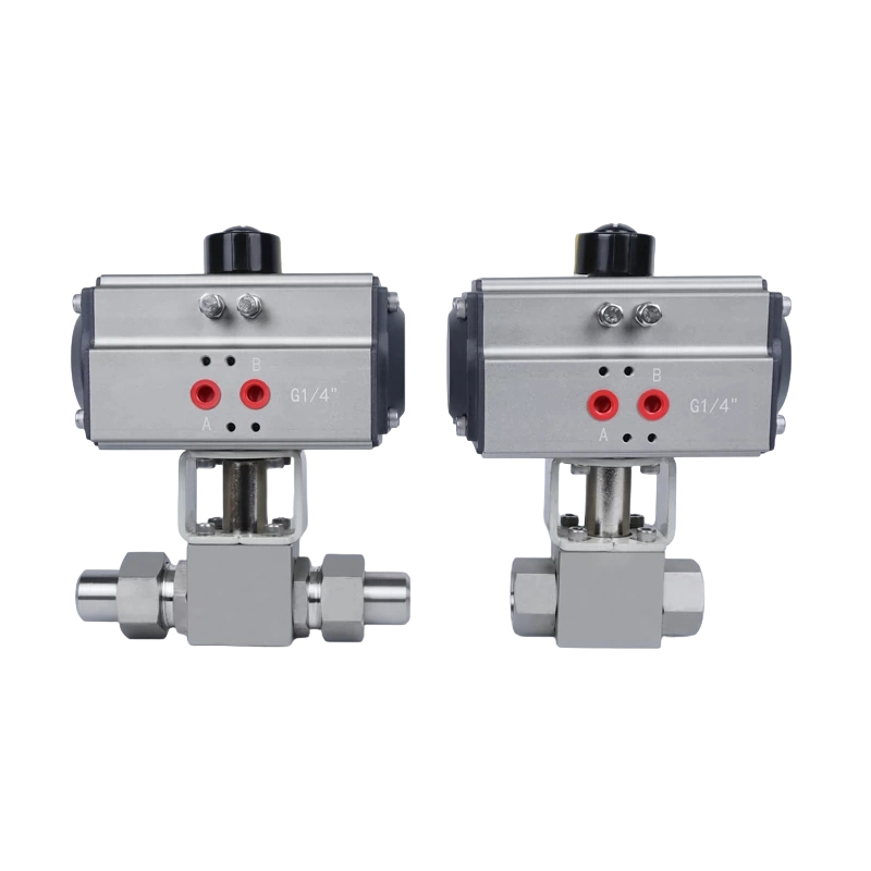
Pneumatic actuators use compressed air, usually between 60 and 100 psi, pushing against a piston or diaphragm to move the stem through a rack-and-pinion or scotch-yoke mechanism. They are favored in oil and gas, refining, and chemical plants where instrument air is already piped everywhere and where fail-safe spring return is a code requirement. A spring-return pneumatic actuator closes the valve automatically the moment air supply is lost, which makes it the default for emergency shutdown gate valves.
Pneumatic actuators are further divided into rack-and-pinion designs, which are compact and common on smaller valves, and scotch-yoke designs, which deliver higher torque output for a given cylinder size and are more common on larger gate and ball valves needing substantial breakaway torque. Double-acting pneumatic actuators use air pressure to both open and close the valve and are typically lighter and less expensive than spring-return units of the same torque rating, but they do not provide an automatic fail-safe position, so they are reserved for applications where loss of air simply means the valve stays in its last position rather than needing to move to a defined safe state.
Hydraulic Actuators
Hydraulic actuators deliver the highest torque density of the three types and are reserved for large-bore gate valves, typically 12 inches and above, on high-pressure pipelines and subsea or offshore platforms where space is tight relative to the torque needed. A hydraulic actuator rated for 20,000 lb-in of torque can be physically smaller than an electric actuator rated for the same output, because hydraulic fluid pressure of 1,500 to 3,000 psi packs far more force into a compact cylinder.
Hydraulic systems can be self-contained, with an integral pump, reservoir, and accumulator mounted directly on or near the actuator, or they can be centrally supplied from a hydraulic power unit feeding multiple actuators across a facility through a manifold. Self-contained units are common where a single critical valve needs independent fail-safe capability, while centrally supplied systems are more economical when many large actuated valves are clustered close together, since one power unit and one set of supply lines can serve all of them.
Comparison of actuator energy sources commonly paired with gate valves
| Actuator Type |
Typical Stroke Time |
Fail-Safe Option |
Best Fit |
| Electric |
15-60 seconds |
Battery backup or capacitor module |
Water plants, general industry |
| Pneumatic |
2-10 seconds |
Spring return on air loss |
Oil and gas, ESD service |
| Hydraulic |
5-20 seconds |
Accumulator-backed fail position |
Large bore, high pressure pipelines |
Valve Construction and Material Choices Behind the Actuator
The actuator only ever performs as well as the valve underneath it, so material and construction choices on the gate valve itself deserve equal attention during specification.
Body and Bonnet Materials
Cast iron and ductile iron bodies cover the bulk of water and wastewater gate valve installations because they offer good strength at a moderate cost and perform well at the relatively low pressures and ambient temperatures typical of municipal water systems. Carbon steel bodies step up to higher pressure and temperature service in process plants and pipelines, while stainless steel and duplex stainless steel bodies appear where the process fluid is corrosive, such as in chemical processing or seawater handling, or where strict cleanliness is required, such as in food and beverage lines.
Gate and Seat Design
Solid wedge gates are the simplest and most widely used design, suited to most general isolation duty. Flexible wedge gates have a slot cut partway through the wedge that lets it flex slightly as it seats, which compensates for minor body distortion from thermal expansion and improves sealing in high-temperature steam and hot water service. Double disc parallel gates use two flat discs that wedge apart against parallel seats, a design that resists binding from thermal expansion better than a single solid wedge in some high-temperature applications, though it is mechanically more complex.
Stem Type: Rising Versus Non-Rising
A rising stem visibly moves up out of the bonnet as the valve opens, giving a clear external indication of valve position even before the actuator's own limit switches are checked, which many specifiers consider a useful redundant indicator. A non-rising stem keeps the stem height constant and rotates the stem within the bonnet instead, which suits buried or vault-mounted applications where vertical clearance for a rising stem is limited.
Packing and Sealing
Traditional braided packing around the stem is inexpensive and field-serviceable but requires periodic adjustment as it wears and can develop minor leakage between adjustments. Many actuated gate valves now specify live-loaded packing, where a spring assembly maintains constant compression on the packing as it wears, extending the interval between manual adjustments and reducing the chance that an actuator drives against an unexpectedly tight or loose stem seal.
Typical body material selection by service condition
| Body Material |
Common Service |
Relative Cost |
| Ductile iron |
Municipal water, wastewater |
Low |
| Carbon steel |
Oil, gas, general process |
Moderate |
| Stainless steel |
Corrosive chemicals, food grade |
High |
| Duplex stainless steel |
Seawater, high-chloride service |
Highest |
How Actuator Torque Is Sized for a Gate Valve
Undersizing the actuator is the single most common cause of premature actuated gate valve failure, so the sizing logic deserves a careful walkthrough rather than a rule of thumb.
- Start with the valve manufacturer's published torque table, which lists breakaway torque, running torque, and seating torque at the valve's rated pressure class.
- Apply a safety margin of 25 to 50 percent above the highest listed torque value, since breakaway torque after years of service is almost always higher than the as-new figure in the catalog.
- Check the actuator's output torque curve across its full stroke, not just the peak rating, because some actuators lose torque near the fully open or fully closed position.
- Confirm the actuator's duty cycle matches the application; a continuous-duty motor is required if the valve cycles more than a few times per hour.
- Review the stem's compressive and tensile strength rating against the maximum thrust the actuator can apply, so the actuator cannot mechanically overpower the stem.
- Confirm ambient temperature range at the install site, since motor torque output and pneumatic seal performance both shift at temperature extremes.
A gate valve that has sat in one position for years often needs 40 to 60 percent more torque to break loose than its nameplate breakaway value, a finding repeated across multiple valve manufacturer engineering bulletins covering long-idle isolation valves in water and wastewater service. This is why experienced specifiers size the actuator against the worst realistic case, the stuck-closed valve after a long outage, rather than the catalog number for a freshly installed valve.
Stem thrust matters as much as torque for rising-stem gate valves. The actuator converts rotary torque into linear thrust through the stem threads, and that thrust must be enough to overcome seat friction and differential pressure across the gate without exceeding the stem's compressive strength rating, which would buckle a long stem on a large valve.
Working Through a Sizing Example
Consider an 8 inch ductile iron gate valve rated for 150 psi, with a manufacturer-published breakaway torque of 450 lb-ft and a running torque of 280 lb-ft. Applying a 40 percent safety margin to the breakaway figure gives a target of roughly 630 lb-ft. An actuator selected from the manufacturer's range should be the next model up whose continuous output torque rating meets or exceeds 630 lb-ft across its full stroke, not merely at one point in the stroke, and whose duty cycle rating supports the expected number of cycles per day in that specific application.
Differential Pressure and Unbalanced Thrust
On valves isolating a charged line against an empty downstream section, the gate must move against unbalanced differential pressure pushing it toward the seat or away from it, depending on direction of travel. This unbalanced thrust adds to the mechanical friction torque already accounted for in the manufacturer's table, and on larger valves at higher pressure differentials it can become the dominant component of total required torque, which is why some manufacturers publish separate torque figures for balanced and unbalanced closing conditions.
Where Actuated Gate Valves Are Used
Gate valves are full-bore, straight-through isolation devices, so actuation adds the most value wherever an isolation point needs to open or close on command without a person standing at the valve.
Water and Wastewater Treatment
Treatment plants use actuated gate valves on raw water intakes, filter backwash lines, and chemical dosing isolation points. SCADA-integrated electric actuators let plant operators sequence backwash cycles automatically across dozens of filter cells, a task that would otherwise need a technician walking the plant floor every few hours.
Oil, Gas, and Petrochemical Pipelines
Pipeline block valves at compressor stations and tank farms are almost always actuated gate or ball valves with pneumatic or hydraulic fail-close function, since pipeline safety practice in most jurisdictions calls for remote and automatic isolation capability at defined intervals along a transmission line.
Power Generation
Boiler feedwater and cooling water systems in power plants rely on actuated gate valves for isolation during startup, shutdown, and emergency trip sequences, where the valve must move within seconds of a turbine trip signal.
Marine and Offshore
Ballast and bilge systems on vessels and offshore platforms use actuated gate valves where space for a hand-operated valve with a long handwheel stem is not available, and where remote operation from a bridge or control room is operationally required.
Mining and Mineral Processing
Slurry transport lines, tailings systems, and process water headers in mining operations use heavy-duty actuated gate valves where abrasive solids content makes frequent manual cycling impractical and where remote control reduces the need for personnel near moving slurry equipment. Knife gate variants, a specialized subtype of gate valve with a sharpened gate face, are common here specifically because they cut through settled solids that would jam a conventional wedge gate.
District Heating and Cooling Networks
Large municipal district heating loops use actuated gate valves at distribution nodes to isolate sections of the network for maintenance without shutting down the entire system, allowing utilities to repair a leak or replace a section of buried pipe while keeping heat supply running to unaffected branches.
Fire Protection Water Supply
Some fire protection water supply mains use actuated gate valves as remotely supervised section isolation points, paired with position monitoring so facility staff can confirm from a central panel that a given section remains open and ready rather than relying solely on a physical tamper switch at the valve location.
Irrigation and Agricultural Water Management
Large-scale irrigation networks use actuated gate valves at canal and pipeline branch points to schedule water delivery automatically on a timer or remote command, reducing the labor needed to manually open and close dozens of distribution points across a large agricultural area during peak irrigation season.
Installation Considerations That Affect Long-Term Performance
An actuated gate valve is only as reliable as its installation, and several details get overlooked in the field.
Orientation matters for stem alignment. Multi-turn actuators mounted on a horizontal pipeline with the stem pointing straight up perform best; mounting at an angle introduces side-load on the actuator output drive and accelerates wear on the stem nut.
Support the actuator weight independently where the line itself cannot carry it. A large electric or hydraulic actuator on a sizeable gate valve can weigh 50 to 200 kilograms, and that load transmits as bending stress into the valve bonnet and the connecting pipe flanges if no additional bracket support is added.
Wiring and conduit runs for electric actuators should account for vibration near pumps and compressors; loose conduit fittings are a frequent cause of intermittent limit switch faults reported in plant maintenance logs. Pneumatic supply lines need a filter-regulator immediately upstream of the actuator, since moisture and particulate in plant air systems is a leading cause of solenoid valve sticking inside the actuator's control package.
Cable and tubing length also affects response time. A pneumatic actuator 100 meters from its air source through small-bore tubing will stroke noticeably slower than the same actuator with a short, properly sized supply line, because the actuator chamber fills at the rate the tubing can deliver air, not at the rate the compressor can produce it.
Coupling Alignment Between Actuator and Stem
The mechanical coupling that connects the actuator's output drive to the valve stem must be square and properly torqued during installation. A slightly misaligned coupling does not always show up immediately; instead it produces gradually increasing wear on the coupling splines and stem nut over months of cycling, eventually showing up as backlash that the limit switches misinterpret as a fully seated position when the gate has not actually reached the seat.
Grounding and Surge Protection for Electric Actuators
Electric actuators installed outdoors or on long cable runs benefit from surge protection at the terminal box, since lightning-induced transients on long buried or overhead cable runs are a recognized cause of control board damage in rural pipeline and water distribution installations. Proper grounding of the actuator housing also reduces nuisance tripping of ground fault protection on the supply circuit.
Vault and Enclosure Drainage
Buried or vault-mounted gate valves with non-rising stems often house the actuator in a below-grade enclosure or extension stem arrangement reaching up to grade level. These enclosures need positive drainage so that groundwater infiltration does not pool around the actuator base, since standing water around even a well-sealed actuator housing eventually finds a way in through cable glands or gasket seams over years of submersion cycles.
Control Signals and Communication Protocols
Actuated gate valves accept control input in several forms, and the choice affects both wiring cost and diagnostic capability.
Common control signal types for actuated gate valves and their typical use case
| Signal Type |
Description |
Typical Use |
| On-off contact |
Simple relay or dry contact closure |
Basic open or close commands |
| 4-20 mA analog |
Proportional positioning signal |
Modulating or partial-stroke applications |
| Fieldbus or Modbus |
Digital network with diagnostics |
Plants with centralized SCADA systems |
| HART |
Digital signal overlaid on analog wiring |
Retrofits keeping existing 4-20 mA wiring |
Note that gate valves are inherently a poor fit for true throttling or modulating duty regardless of which signal drives them. A gate valve's flow-versus-travel curve is highly nonlinear, with most of the flow change happening in the last 10 to 20 percent of stem travel, so even when fitted with an analog positioner, gate valves are typically commanded fully open or fully closed rather than held at an intermediate position. Applications needing real modulation generally use a globe or control valve instead, with the actuated gate valve reserved for upstream or downstream isolation.
Local Control Stations and Manual Override
Most actuated gate valves retain a local control station mounted near the valve with open, close, and stop pushbuttons, plus a selector switch for local versus remote control. This allows maintenance staff to operate the valve directly during testing or troubleshooting without needing to issue a command through the control room, and the selector switch position itself is typically wired back as a status point so the control room knows when a valve has been taken out of remote control.
Wireless and Battery-Powered Control Options
Remote pipeline and irrigation sites without nearby power or hardwired communication increasingly use solar-powered electric actuators paired with cellular or radio telemetry, reporting valve position and battery status back to a central monitoring system on a scheduled interval. This avoids the cost of trenching power and signal cable to isolated valve locations that may be kilometers from the nearest grid connection.
Redundancy in Safety-Critical Loops
Where an actuated gate valve performs an emergency isolation function, the control loop often includes redundant elements, such as dual solenoid valves on a pneumatic actuator or two independent limit switch circuits feeding separate safety system inputs, so that a single component failure in the control chain does not silently disable the valve's ability to close when commanded.
Common Failure Modes and What Causes Them
Most actuated gate valve failures trace back to a small number of recurring root causes rather than random component defects.
Actuator Stalling on a Stuck Gate
When the gate has not moved for an extended period, debris, scale, or corrosion can bond the gate to the seat. An undersized or aging actuator stalls under the load, trips its motor overload, and the valve never completes its stroke. This is the failure mode the torque safety margin discussed earlier is meant to prevent.
Limit Switch Drift
Mechanical limit switches that sense full-open and full-closed position can drift out of calibration over hundreds of cycles, especially on actuators exposed to vibration. A drifted switch reports a false closed signal while the gate is still slightly open, which is a serious safety concern on isolation duty.
Seal and Gasket Degradation in Pneumatic Actuators
Piston seals inside pneumatic actuators harden and crack over years of thermal cycling, leading to internal air leakage that shows up as slower stroke times long before the actuator fails completely. Field technicians often catch this early by tracking stroke time trends rather than waiting for an outright failure.
Moisture Ingress in Electric Actuator Housings
Outdoor electric actuators with degraded gasket seals allow condensation to build inside the gear case, corroding internal wiring and gear surfaces. IP68-rated actuator enclosures resist this far better than IP54 or IP55-rated units in outdoor or submerged service, which is why specification sheets for buried or vault-mounted valves should always call out the higher ingress protection rating.
Wedge or Gate Jamming from Thermal Expansion
On hot water, steam, or thermal process lines, repeated heating and cooling cycles can cause the gate and body to expand at slightly different rates, gradually tightening the fit between gate and seat until the actuator can no longer free the gate without exceeding its torque rating. Flexible wedge gate designs reduce this risk but do not eliminate it entirely, especially on valves that cycle infrequently and sit at one temperature extreme for long stretches.
Hydraulic Fluid Contamination
In hydraulic actuator systems, contaminated or degraded hydraulic fluid accelerates wear on internal seals and valve spools inside the actuator's control manifold, leading to sluggish or erratic stroke behavior. Routine fluid sampling and filter element replacement on the hydraulic power unit catches this trend before it produces an outright actuator malfunction.
Control Wiring and Terminal Corrosion
Terminal connections inside actuator control compartments that are not properly sealed during installation are a common source of intermittent signal faults, particularly in humid or coastal environments where airborne salt accelerates corrosion on exposed terminal screws and ring lugs.
Troubleshooting Guide for Common Symptoms
The following table maps symptoms commonly reported on actuated gate valves to their most likely root cause, as a starting point for field diagnosis before deeper investigation.
Symptom-based troubleshooting reference for actuated gate valves
| Symptom |
Likely Cause |
First Check |
| Valve will not move at all |
No power, no air supply, or tripped overload |
Supply voltage or air pressure at the actuator |
| Stroke time has gradually increased |
Internal seal leakage or dried gear lubricant |
Compare current stroke time against commissioning baseline |
| Valve stops short of full close |
Limit switch miscalibration or coupling backlash |
Manual stroke with visual confirmation at the gate |
| Motor overload trips during closing |
Stuck gate exceeding actuator torque rating |
Torque switch setting and gate condition |
| Intermittent loss of remote signal |
Corroded terminal connection or loose conduit fitting |
Terminal compartment for moisture or corrosion |
| Visible leakage at the stem |
Worn packing or loose packing gland |
Packing gland tightness and packing condition |
Cost Factors and Total Cost of Ownership
The purchase price of an actuator is only one part of the total cost a facility carries over the life of an actuated gate valve installation, and a narrow focus on upfront price has led many projects to select an actuator that costs more to operate than a slightly more expensive alternative would have.
Upfront Equipment and Installation Cost
Electric actuators generally carry the lowest upfront equipment cost for small to mid-size valves, since they avoid the need for compressed air piping or a hydraulic power unit. Pneumatic actuators add the cost of air supply infrastructure if it does not already exist at the site, while hydraulic systems carry the highest upfront cost due to the pump, reservoir, and piping required, though that cost is often justified on large valves where the torque requirement makes electric or pneumatic options impractical.
Energy Consumption
Electric actuators only draw power during the brief stroke itself, making their running energy cost negligible in most applications. Pneumatic systems carry a hidden ongoing cost in the form of compressor electricity and compressed air leakage, since even a well-maintained plant air system commonly loses a meaningful percentage of generated air to leaks throughout the distribution network, a cost that scales with the number of pneumatic devices connected to that system.
Maintenance Labor and Spare Parts
Electric actuators typically need less frequent hands-on maintenance once correctly commissioned, mainly periodic lubrication and limit switch verification. Pneumatic actuators need regular attention to filter-regulator elements and periodic seal replacement. Hydraulic systems require fluid sampling, filter changes, and pump maintenance on top of the actuator itself, which raises the ongoing labor cost compared to the other two actuator families even though hydraulic units themselves are mechanically robust.
Downtime Cost of Failure
The most significant cost driver is often not the actuator at all but the cost of process downtime if the valve fails to operate when needed. A relatively small additional spend on a higher safety margin actuator, better ingress protection rating, or redundant control wiring is frequently justified purely by the avoided cost of a single unplanned shutdown on a critical isolation point, which is why many specifications for safety-critical valves intentionally exceed the minimum torque and protection rating that would technically suffice for normal operating conditions.
Maintenance Schedule and Inspection Practices
A maintenance program built around actual operating conditions outperforms a generic calendar-based schedule.
- Cycle test idle valves at least quarterly, since a gate valve that never moves is the one most likely to seize when an emergency calls for it.
- Check actuator lubrication on electric units annually, or per the manufacturer's gearbox oil interval, since dried-out gear lubricant is a common cause of increased running torque over time.
- Inspect pneumatic supply tubing and filter-regulator elements every six months in dusty or humid plant environments.
- Verify limit switch calibration during every scheduled valve stroke test, not only after a reported fault.
- Record stroke time at each test and trend it, since a gradual increase in stroke time is an early warning sign across all three actuator types.
- Sample hydraulic fluid annually on hydraulic actuator systems and replace filter elements according to the power unit manufacturer's recommended interval.
- Inspect and re-tighten packing gland nuts during routine rounds, since a slowly weeping packing gland is far easier to correct before it becomes a steady leak.
- Check terminal compartment seals and cable gland tightness during annual electrical inspection, especially on outdoor or submerged installations.
Partial stroke testing has become standard practice on safety-critical actuated gate valves, particularly emergency shutdown applications. Moving the valve 10 to 20 percent off its seated position and back confirms the actuator and gate are not stuck, without fully interrupting process flow, and this technique is widely documented in process safety engineering literature covering shutdown valve testing intervals.
Record Keeping and Trend Analysis
Maintenance teams that log stroke time, torque switch trip frequency, and motor current draw at each scheduled test build a performance history for every actuated valve in the facility. Comparing each new reading against that valve's own historical baseline, rather than against a generic published specification, catches gradual degradation far earlier than waiting for an outright failure, since the rate of change for an individual valve is usually a better early indicator than its absolute value at any single point in time.
Selection Checklist Before Specifying an Actuated Gate Valve
Pulling the previous sections together, a practical specification process moves through these checks in order:
- Confirm line pressure, temperature, and media compatibility with the valve body and trim material.
- Pull the manufacturer torque table at the valve's full pressure rating, not a reduced or nominal figure.
- Add a realistic safety margin that accounts for long idle periods between cycles.
- Decide fail-safe behavior required on loss of power or air, and select actuator type accordingly.
- Match the control signal type to existing plant infrastructure to avoid unnecessary signal conversion hardware.
- Specify enclosure ingress protection rating based on actual outdoor, indoor, or submerged exposure.
- Confirm gate, seat, and body material compatibility with the process fluid and expected temperature range.
- Evaluate total cost of ownership, not just upfront equipment price, particularly for high-cycle-count applications.
- Plan the cycle testing and lubrication schedule before commissioning, not after the first failure.
Treating actuator selection as a sizing exercise built on the valve's real torque demand, rather than a generic accessory choice, is what separates an actuated gate valve installation that runs for decades from one that needs unplanned intervention within its first few years of service.
Frequently Asked Questions
What is the difference between a manual and an actuated gate valve?
A manual gate valve is operated by a handwheel or lever turned by a person, while an actuated gate valve has a motorized, pneumatic, or hydraulic actuator that performs the same opening and closing motion automatically in response to a control signal.
Can an existing manual gate valve be retrofitted with an actuator?
Yes, in most cases. The valve's stem and bonnet need a compatible mounting flange, and the actuator must be sized against the valve's specific torque table; many actuator manufacturers supply standardized mounting kits for common gate valve bonnet patterns.
How long does a typical actuated gate valve last before major overhaul?
Service life varies widely by application, but well-maintained actuated gate valves in clean, non-abrasive service commonly run 15 to 25 years before requiring major overhaul, while units in slurry, scaling, or corrosive media may need internal parts replacement much sooner.
Is a pneumatic or electric actuator better for a gate valve?
Neither is universally better; pneumatic actuators suit sites with existing compressed air and a requirement for spring-return fail-safe closing, while electric actuators suit sites without compressed air infrastructure where simple power and signal wiring is preferred.
Why does an actuated gate valve sometimes fail to fully close?
The most frequent causes are an undersized actuator stalling against a stuck or debris-fouled gate, a miscalibrated limit switch reporting a false closed position, or mechanical binding from misaligned stem coupling between the actuator and the valve.
Can actuated gate valves be used for flow modulation?
Gate valves are not well suited to sustained throttling because their flow-versus-travel relationship is highly nonlinear, with most flow change occurring near the end of stem travel; applications needing true modulation typically use a globe or control valve instead.
How often should an actuated gate valve be cycle tested?
A quarterly cycle test is a common baseline for valves that otherwise sit idle for long periods, though safety-critical shutdown valves are often partial-stroke tested far more frequently, sometimes monthly or even weekly, depending on the risk level of the service.
What ingress protection rating should an outdoor actuator have?
Outdoor or vault-mounted electric actuators generally warrant at least an IP67 rating, with IP68 preferred for units that may experience temporary submersion, since lower-rated enclosures are more prone to moisture ingress over years of weather exposure.
Does a knife gate valve count as an actuated gate valve?
Yes, a knife gate valve is a specialized gate valve subtype with a sharpened gate face designed to cut through slurries and fibrous solids, and it can be fitted with the same electric, pneumatic, or hydraulic actuator types described throughout this article.
What happens to a spring-return pneumatic actuator if instrument air pressure drops gradually rather than failing suddenly?
As supply pressure falls below the actuator's minimum operating threshold, the spring begins to overcome the weakening air pressure and drives the valve toward its fail-safe position before air supply is fully lost, which is why minimum supply pressure should always be checked against the actuator's specification rather than assumed adequate simply because some air pressure is still present.



 English
  русский
  Español